Wednesday, December 28, 2011

progress on transverter

I finally found some time to work on the transverter.
Now the transverter/cb radio is able to receive 160-10 meter.

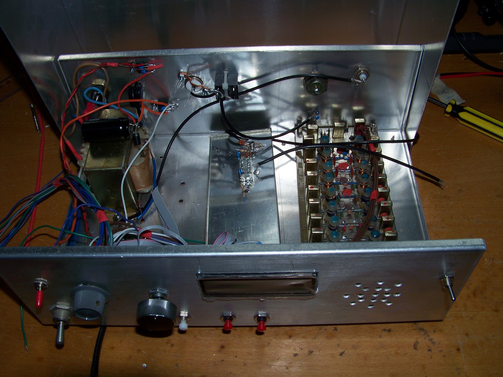
It consists of the folowing parts:
LO: sdr kits si570 vfo
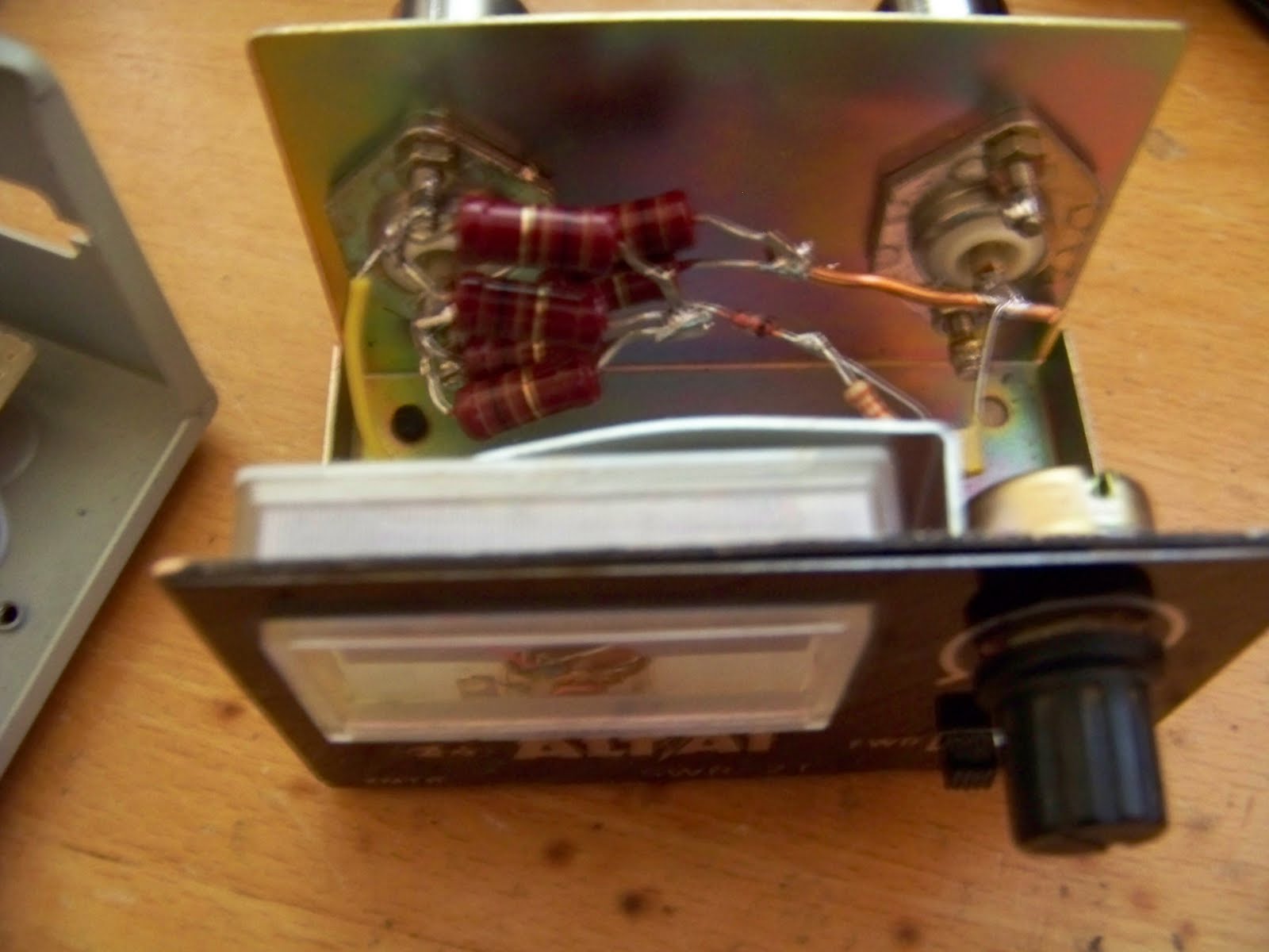
Switchable bandpass filter: comes from russian ham parts
Power supply: Transformer taken from cb power supply
The Mixer is a sbl-1.

The LO signal is amplified by a bfy-90 amplifier. This signal drives the mixer.
The signal from the antenna is filtered by the bandpass filter. This board has a preamp as well. The filtered signal is connected to the mixer. The output of the mixer goes to the cb radio.
That is all that is needed to make a transverter. In this stage it is even able to transmit. Although the rf signal is very small (50mV pp).

The reception seems fine. But transmitting a clean signal can be a problem. On 24 and 28 MHz the 27 MHz signal may be too strong. Filtering it can be a problem.
I will give it a try anyway.

If it fails I will try the trick I described before. I will make a transverter from 27 MHz to 75 MHz. The LO for that transverter will be a fixed fixed frequency oscillator. Then I will use the VFO to mix the filtered HF signals to 75 MHz.
Supression of the 27 MHz signals is much easyer this way as 27 MHz is far away from 75 MHz
In fact I will have two transverters in series.


Friday, May 20, 2011

SWR bridge 160 meter

I need a SWR meter for the 160 meter transmitter. So I build one in an old 27 Mhz CB SWR meter enclosure. It is a ressitortype  bridge.It looks like this one:
I use 2 100Ohm resitors in parallel to make the 50 Ohm . Those resistors can handle 1 Watt so I can use the bridge for 5 watt QRP transmitters.

A bridge like this limits the mismatch for the TX. That is ideal for testing homebrew transmitters on air. 

It is no ready yet I need to add a switch to bypass the bridge when tuning has finished.  The bridge consumes 75% of the power.  So a bypass switch is needed.

PLL for AM transmitter

I Build a synthesizer for the AM transmitter. The diagram was found at.
Nederlands forum over oude radio's It is pretty straight forward. A refrence oscillator, a 4046 PLL including VCO and a progrogrammable divider.

I have build a similar PLL in the past. using a seperate VCO and 74192 dividers. It was not hard to build but the vco did not work. I had to use a  15K resistor form pin 12 to earth. This also limits the VCO range to 800 KHz to 2 MHz. That should improve the quality of the signal as well. I am pleased with the result. I listened to the signal in cw mode. It sounds clean.

I have used a different xtal. Now my stepsize is 7 KHz instead of 9 KHz. That is Ok for 160 meter.

The box that contains my 1.8 Khz AM transmitter has no more room so I have mounted it on the back. It is in a metallic enclosure so it should be fine.

ic-255

I bought a IC-255E on Ebay for sentimental reasons. I used to own an IC-260E. That was my first transceiver. I worked during the summer holliday to finance it. 

The radio did not come with the  mic so I had to find one myself. Fortunately I have quite a lot of microphones for CB radio's. The Icom however needs an amplified mic. So I had to build a amplifier in the mic. Icom was kind enough to provide the schematic diagram. I did no have the transistor so I used a bc547 instead. It worked. Modulation sounds great.

The Icom was deaf when it arrived. No output was available either. It turned out that the tracks on the output filter PCB were damaged. Most of them were loose. That could be fixed easily.

Another problem was the receiver. It was 5 KHz off frequency.  Fortunately the manual provides some pictures of the internal controls. So I could fix that problem too.

The only remaining problem is the duplex switch. The control need to be cleaned internally as it cracks. The set switches back and forth between duplex and simplex. I have to find a some kind of spray.

Saturday, May 7, 2011

160 meter AM using tuner.

I started to build a simple 160 meter AM transmitter using a old tuner. Target output is 1 Watt.

The plan was to build the complete transmitter in the tuner. Unfortunately It did not fit in my tuner. So I put it in a old printer switch box.

The design is straight forward. The signal out of the tuner is amplified by a few bc547 amplifiers. then that signal is used to drive a 4427 mosfet driver. This driver drives a IRF510. It works in Class D. The output is filtered by a 7 element Lowpass filter. Modulation is done by a darlington transistor. That works as a modulatable power supply.

At this stage it is functional but there is room for improvement. Modulation depth is 75 procent maximum. Harmonic suppression can be improved. Especially between 15 MHz and 25 MHz. The signals are 40 db below carrier. That is probably good enough but I think it can be improved easily.

500 KHz on hold

I shelved my 500 KHZ project. It seems we are not going to get 500 KHz access after all.
So I will focus on other projects.

Sunday, March 6, 2011

capacitor problems

Capacitors still cause problems. I made series circuit using 3 capacitors. Then I used  3 of those circuits parallel.
Unfortunately they still get too hot .
So I switched to 400 Volt mks capacitors. Those too get too hot.  I found out on a forum that I need polypropylene types. Next week I will try to buy them. I hope the  local store sells them.

In the meantime I will try to improve the quality of the signal at the drain. It does not look like a square wave.
Besides that at some voltages It seems to produce spurious signals.  I had a look at other designs. Most of them load the drain with a RC series circuit. I Will try that too.

Wednesday, February 23, 2011

60 Watt on 500 KHz

The  new toroids  FT240-31 and FT 140-32. Using these is overkill for the power levels I hope to reach.
In the future I will try to get some more power. Then I do need them.

Using those cores improved the amplifier dramatically. Now I can get at least 60 Watt sinus output. A bit more when it has warmed up ,which seems strange.

While I was waiting for the core to arrive I build a 7 elements lowpass filter. I almost burned up the capacitors when I applied power to it. They can not handle 100 Volts thats is clear. I have no idea how much they can handle. I bought a bag full of them on Ebay. No info is available.  So I used a series circuit  of 2 capacitors to decrease the voltage. That worked quite well. They still get to hot though. After a minute full power the output is no longer a clean sinus. So eventually I will use a series circuit of 3 or more capacitors.  

Tuesday, February 8, 2011

Power amplifier continued

The TC4427 diver ic's have arrived. The same night I tried one out. It was a success. The efficiency of the amplifier increased dramatically. Now the dummyload gets warm instead of the FET's.  It is hard estimate the efficiency as the output signal is not a sinus nor a block. It seems I can get 25 watt output while the FETS stay cool.

I am not out of the woods yet as the ringcores of the output transformers get hot. New bigger ones have been ordered. So I have to wait for them to arrive. 

Saturday, January 29, 2011

Power amplifier

Power amplifiers usually cause the most problems, this one is no exception.

I retrieved some cores from a PC power supply. They seem to work. For the time being the amplifier uses 2 IRF510 mosfets. I will switch to more powerful types later. The amplifier should work in class D.  The amplifier puts out 30 Watts but efficiency is low 60%.

The problem seems to be the mosfet drivers. I tried to drive them directly from TTL at 6 Volts. It did work but efficiency was 40% or less. Then I tried 2 driving transistors. That improved the efficiency  but it is still not good enough. I will try TC4427 drivers.

Sunday, January 16, 2011

500 KHz bandpass filter and preamp

I made a bandfilter for 500 KHz. I have also added a preamp as it turned out the filter has 6 db attenuation.
The preamp has to compensate for the loss. It also has to compensate for the loss in the mixer.
It seems to work fine but I have to test the noise behavior. Gain is 6db, the -6db band width is 10 KHz.

I have several 455 KHz If transformers. They can be tuned to 500 KHz easily. However matching to 50 Ohm is difficult. I also tried filters using FT50-43 cores but that was a bad idea. The -6db bandwidth was 100 KHz.  Matching to 50 Ohm was OK though. So I use one FT50-43 filter to match the impedance of the IF transformers.

Alternatively I could have used air coils. Then the filter would be bulky.

The transistor get a bit hot I will keep an eye on it. I may have to use a heat sink. 

Friday, January 7, 2011

status 500 KHz project

This is the current state of the project. TX works for CW . Reception works but bandfilter for RX won't fit in this tin box. Next step is to add the AGC amplifier.