
Sunday, February 16, 2014
a new toy
I have a new toy. A HP spectrum analyzer that works up to 350 MHz.
I already own a spectrum analyzer. It is an Atten that works from 0 to 1000MHz. It only has 1 filter that is more than 200 KHz wide. It is usable but this HP is much better.

Saturday, February 15, 2014
TR7200
Two years ago I bought a Kenwood TR7200. It is a well know 2 meter FM radio. It uses xtals

I did not use it much as I only have 2 channels that are usable.
The other xtals were for USA frequencies in the 146 MHz range.
Now I bought some xtals for it. Now I can use the following frequencies.
I did not use it much as I only have 2 channels that are usable.
The other xtals were for USA frequencies in the 146 MHz range.
Now I bought some xtals for it. Now I can use the following frequencies.
- 145.500
- 145.550
- 145.400
- 145.350
CHN transceiver update
I did some rpairs on the CHN transceiver.
HF PA's usually causes head ages. This one is no exception.
I can get 14 watts CW on 80 meters. On 20 meter it was just 4-5 watts. SSB PEP is lower.
at 80 meter I can get 6 watt. on 20 meter it is about 2 Watt max.
In CW mode the signal does not go through the xtal filter. It is much stronger than the SSB signal.
So I need to get some more gain of the ssb signal.
The PA suffered from some strange distortion. At full power It works for 1 second. then the sinus starts to deteriorate. It does not seem to be oscillation. After a small pause I can get another second with a clean signal.
I tried to solve it using forced cooling. It helped but it is was not enough.
The power transistors 6xBD137 were mounted on a small heatsink. No cooling paste was used.
I think this causes the problem. A hotspot temperature is getting to high. That may be the reason for the deteriorated signal. So I applied some paste.
I also mounted two 10 Ohm resistors in series over the input transformer of the PA.
This reduces the power to 7-8 Watt but the signal is clean. It looked OK even when the dummyload was removed. Usually PA's start to oscillate when I try this.
I don't need a lot of power though. I need only a few watts as input for a bigger amplifier. So I won';t try to getr max power out of it
Things to do.
- -X/RX relais was wired incorrectly. Fixed that
- It contains a variable capacitor at the front. It is used to peak output for the 80 meter band.This capacitor was not working correctly. Fortunately I had a similar capacitor in the junkbox box.That one worked OK.
- The IF board needed alignment. Fixed that.
- Improved decoupling of PA board.
HF PA's usually causes head ages. This one is no exception.
I can get 14 watts CW on 80 meters. On 20 meter it was just 4-5 watts. SSB PEP is lower.
at 80 meter I can get 6 watt. on 20 meter it is about 2 Watt max.
In CW mode the signal does not go through the xtal filter. It is much stronger than the SSB signal.
So I need to get some more gain of the ssb signal.
The PA suffered from some strange distortion. At full power It works for 1 second. then the sinus starts to deteriorate. It does not seem to be oscillation. After a small pause I can get another second with a clean signal.
I tried to solve it using forced cooling. It helped but it is was not enough.
The power transistors 6xBD137 were mounted on a small heatsink. No cooling paste was used.
I think this causes the problem. A hotspot temperature is getting to high. That may be the reason for the deteriorated signal. So I applied some paste.
I also mounted two 10 Ohm resistors in series over the input transformer of the PA.
This reduces the power to 7-8 Watt but the signal is clean. It looked OK even when the dummyload was removed. Usually PA's start to oscillate when I try this.
I don't need a lot of power though. I need only a few watts as input for a bigger amplifier. So I won';t try to getr max power out of it
Things to do.
- Get more gain for SSB.
- Carrier is not suppression is not good om 20 meter. It is quite allright on 80 meter though.
- RIT works but I can not tune to the same frequency I had when RIT is off.
- Find an enclosure for the set.
Thursday, February 6, 2014
chn-8020 transceiver
I just bought a defect chn-8020 transceiver from a fellow ham.


The transceiver is a home made transceiver designed in 1980 ? by PA0CHN It covers 2 bands, 20 meter and 80 meters. ssb/cw 10W output. IF is 9 MHz.'
It iused to be popular here in the netherlands.
This unit was not in a good state. It needs a lot of work. It was not completed by the builder.
It was not build by the ham I bought it from so its history was unclear.
Some components were missing and some wiring was missing or just incorrect.
Fortunately the difficult components were mounted including the 9MHz xtal filter.
When I fired it up it did not do much. A light was working and i heared some cracking noise from the speaker while turning the volume knob.
I found that the VFO did work. The audio module worked a bit after cleaning the contacts.
The audio module also contains the sidband xtal scillators and a mixer. So I applied a very strong 9 MHz signal on the input. I could hear it weakly from the speaker. So it has some life in it
The transceiver is a home made transceiver designed in 1980 ? by PA0CHN It covers 2 bands, 20 meter and 80 meters. ssb/cw 10W output. IF is 9 MHz.'
It iused to be popular here in the netherlands.
This unit was not in a good state. It needs a lot of work. It was not completed by the builder.
It was not build by the ham I bought it from so its history was unclear.
Some components were missing and some wiring was missing or just incorrect.
Fortunately the difficult components were mounted including the 9MHz xtal filter.
When I fired it up it did not do much. A light was working and i heared some cracking noise from the speaker while turning the volume knob.
I found that the VFO did work. The audio module worked a bit after cleaning the contacts.
The audio module also contains the sidband xtal scillators and a mixer. So I applied a very strong 9 MHz signal on the input. I could hear it weakly from the speaker. So it has some life in it
Monday, November 19, 2012
Digital modes
Now I can make a restart in digital modes.
An old pentium PC was available for the coding and decoding. The transceiver I use is an old ICOM IC-730. I also have an IC-817 this one works ok but the IC-730 has a better receiver.
A lot of nice freeware programs exists. I have chosen fldigi for most digital modes. Fldigi does not support all modes so I use different programs for modes WSPR,JT65 and ROS.
For a while I thought that the signallink was partly broken. It worked fine for most programs butI did not see a signal on the right input. It turned out that is was normal as the signallink is a mono device. Unfortunately one of the JT65 programs could not be used because of this. I read that the developer is going to update the program because of this issue. In the mean time I use a different program for JT65.
The modes That I use are: WSPR, PSK31, JT65 and ROS.
below is a picture of a part of the shack

Sunday, March 25, 2012
standard c828m
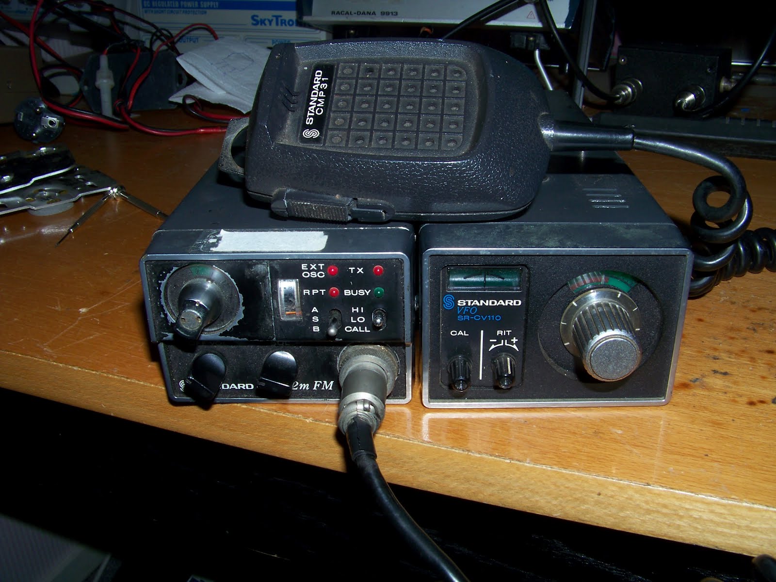
I bought this radio on a hamfest. It was realy cheap, just 10 euro's. I was told that it still worked.It does not look verry pretty But what can you expect for 10 euro.
Well it did work. The transmitter worked quite well. Output was down to 5 Watts so I realigned it a bit. Now the output is 8 watts. I could get a bit more but then the harmonics are to strong.
All 12 xtal positions were filled. That is a nice bonus. It has some simplex channels , some repeater channels and 144.800.
The receiver had problem, it was deaf. It needed 50 uV for a readable signal.
I found out that the pre amplifier transistor had been replaced by a bf??? I tried to find out what the original transistor should be. Finally I found the manual at mods.dk. The transistor should have been a 2sk19. I had no such device in the junkbox so I tried something else. It turned out that the j310 could be used as well. Now the sensitivit is ok. It needs 0.3uV for a readable signal. This is acceptable.
Wednesday, February 22, 2012
dds project

On Ebay I found dds pcbs. Those boards contain a 9850 dds chip and an oscillator.
It can be used for a synthesyzer from Hz up to to 40 MHz and more. I bought a few for my projects.
The DDS needs to be programmed. To do that I used a PIC based microcontroller board that I made for my spectrum analyzer project.
Programming the DDS is not that hard. The frequency in the DDS is controlled by writing a value to a 32 bit register. A few control bits must be set and that is it.
The 9850 is a well know chip so some sample code was available.
The biggest Software challenge was to display the frequency correctly. Some floating point calculations had to be done. Unfortunately the double datatype was to small for the calculation so I had to split it up.
Now It works prety good. This project can be the base for projects that need a synthesizer. First candidate is my 70 MHz to cb transverter. I need a 43 MHz signal for it. The DDS can deliver it but the output must be filtered using a bandfilter or a pll. This is needed because of the spurious signals that the DDS generates for signals >30 MHz.
Another project could be a 0-30 MHz CW transmitter. The spurious signals are within legal limits. A lowpass filter however is needed.
Subscribe to:
Posts (Atom)